PRODUCT
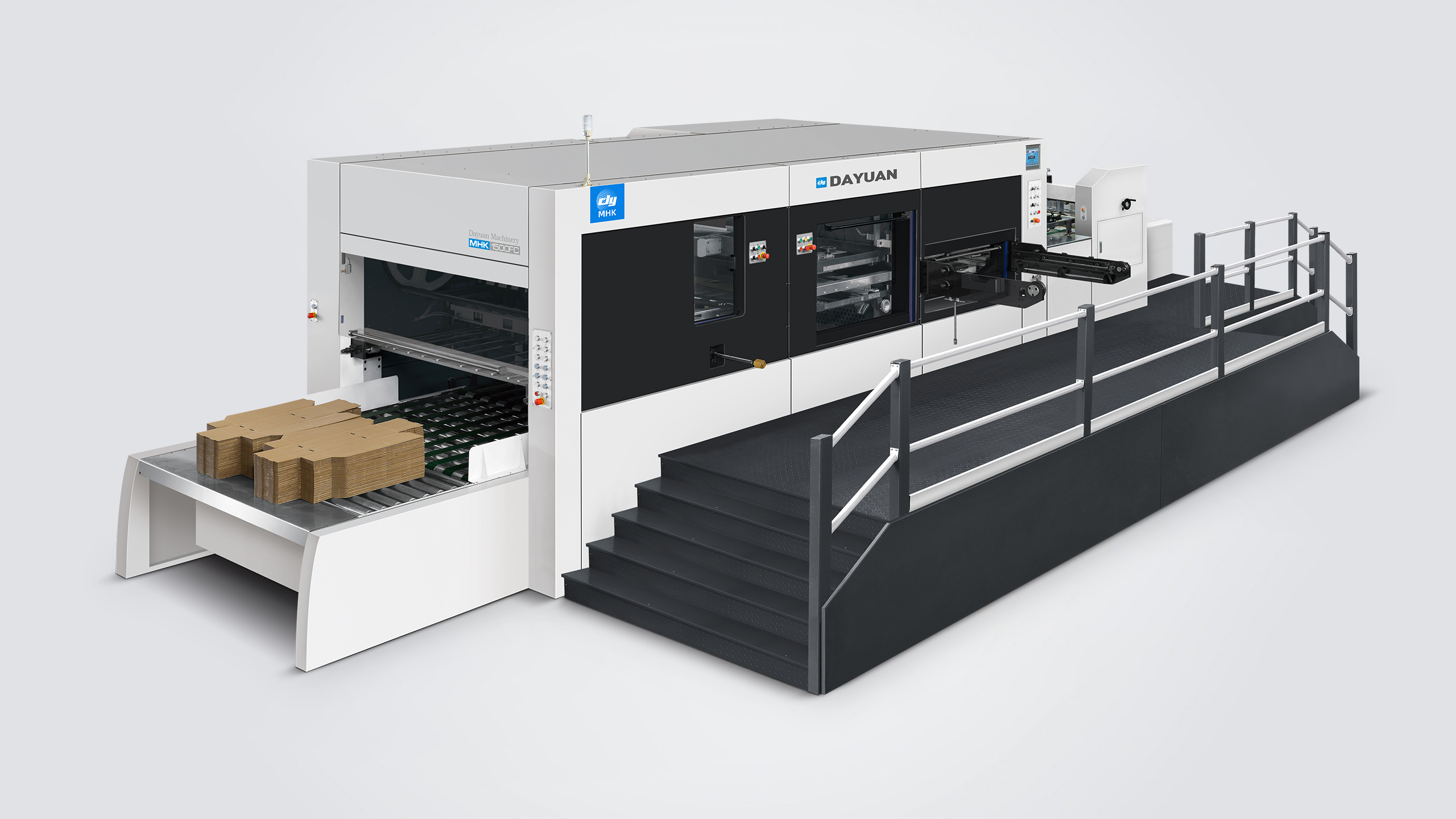
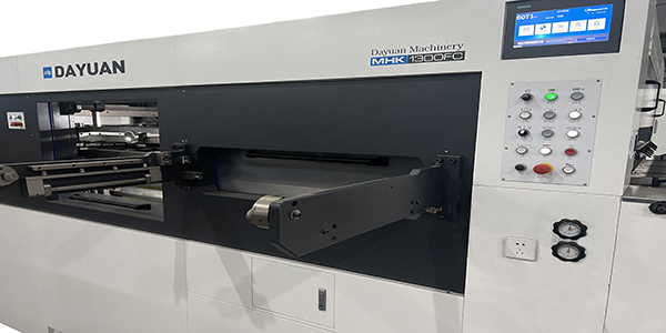
MHK 1300FC/1350FC/1500FC/1650FC
Automatic Die Cutting & Creasing Machine with Stripping (Lead Edge Feeder)
Features Introduced
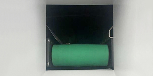
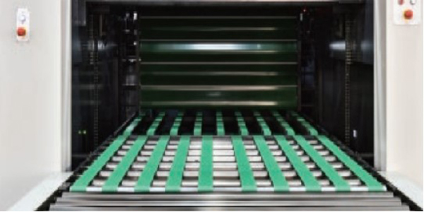
Lead edge feeder
● Top gear and precise Lead Edge Feeder design, allowed consistent feeding with various quality corrugated board.
● New technology polyurethane wheel surface with grid lifter and air cushion ensure smooth feeding and accurate alignment even warped board.
● Fine vacuum suction adjustment through inverter adapts to wide range stock from F flute to double wall corrugate.
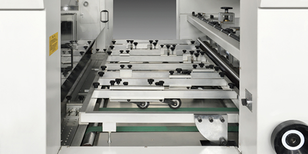
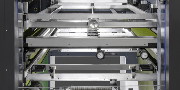
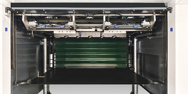
Sheet transmission and alignment section
● Selectable left and right side push lays to ensure accurate alignment.
● Advanced non-stop adjustment of feeding timing, reduce down time.
● Front gauge non-stop back and forth adjustable to accommodate variation in gripper margin.
Die cutting unit
● Die-cutting base plate and knife template rotary device.
● The connection between the die cutting plate and the die cutting frame adopts the form of grasping snail and screws, adopt central positioning system, which is fast and accurate.
● The die-cutting plate frame and the die-cutting steel backing plate are locked by the Japanese SMC gas volume regulator to avoid the situation that the locking and installation of the upper frame is not in place, and effectively avoid the loss caused by the operation of human factors.
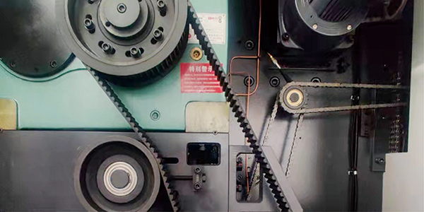
Timing belt drive, Intermittent mechanism
● Imported synchronous belt and pulley drive.
● Imported intermittent splitter.
● Imported torque limiting overload protector.
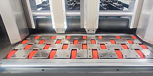
Stripping section
● Upper waste transmission mechanism.
● Users can choose whether to use the stripping function by lifting upper stripping frame.
● Pull-out drive mechanism with quick locking function for intermediate negative stripping frame.
● Lower stripping transmission mechanism.
● The stripping plate is installed using a centerline quick-positioning method, enabling operators to mount it rapidly and improve changeover efficiency.
Gripper margin stripping device
The gripper stripping device can automatically convey gripper waste edges out of the machine and achieve four-frame stripping.
Batch delivery conveying unit(Optional)
The automatic batch delivery lifting table device can automatically set the number of stacked sheets, and cooperate with the conveyor belt to convey the paper outside the machine. The paper surface is not easily scratched or abraded during the paper stacking process (Special for batch delivery, optional)
Non-stop stacking delivery unit
High pile stacking table adopts lifting device, paper delivery structure can pull the whole pile of paper out of the machine.Main delivery device and auto non-stop roll-up curtain type auxiliary collecting device switch automatically without any operation, significantly enhancing productivity.
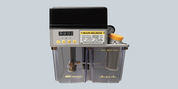
Auto lubrication system
The whole machine adopts a centralized automatic oil supply system to ensure that the transmission parts are not short of oil.
Configurations
| Conveying Unit | MHK-1300FC/1350FC/1500FC/1650FC |
| 01. High-speed and precise lead edge feeder with high feeding accuracy, strong suction power, anti-slip performance, and stable transportation for various types of corrugated board | 〇 |
| 02. New technology polyester wheels with grid lifter and air cushion ensure smooth feeding and accurate alignment even when dealing with warped board | 〇 |
| 03. Fine vacuum suction adjustment through inverter adapts to wide range stock from F flute to five-layer corrugate paper | 〇 |
| 04. Electric side pushing baffles (both the left and right sides) | 〇 |
| 05. The left and right baffle can be adjusted either independently or synchronously. The slanted front baffle can be fine-adjusted in both forward/backward and upward/downward directions, reducing pressure of the paper under the paper pile for smoother feeding | 〇 |
| 06. Right and left side positioning push gauge to ensure precise side positioning of the cardboard | 〇 |
| 07. The pallet height can be adjusted according to the paper quality and thickness, making the paper feeding smoother and more stable | 〇 |
| 08. The fine-tuning device for the front baffle’s front and rear positions can be finely adjusted according to the gripper margin size | 〇 |
| 09. Non-stop adjusting device for feeding step | 〇 |
| Die-cutting Unit | |
| 01. The entire machine casting is made of QT-700-2 nodular cast iron | 〇 |
| 02. Imported worm gear, worm gear and 40cr crankshaft | 〇 |
| 03. A complete set of imported anodized aluminum alloy gripper bars and positioning structure, fine steel gripper teeth and supporting gripper plates. The gripper bars adopt an adjustable gripper bar structure | 〇 |
| 04. Imported main drive chain | 〇 |
| 05. Imported intermittent splitter | 〇 |
| 06. Imported synchronous belt and pulley drive | 〇 |
| 07. Imported torque limiting overload protector | 〇 |
| 08. Imported pneumatic clutch brake device | 〇 |
| 09. Pressure regulating device, which can realize accurate control of pressure through PLC touch screen buttons | 〇 |
| 10. Die-cutting base plate and die mould rotary device | 〇 |
| 11. The connection between the die cutting plate and the chase adopts the form of grasping snail and screws, adopt central positioning system, which is fast and accurate | 〇 |
| 12. The die-cutting chase and the lower mat are locked by the Japan SMC gas regulator, which can prevent improper locking of the upper frame caused by human error during installation | 〇 |
| 13. Japan SMC air pressure detection device, low air pressure alarm | 〇 |
| 14. Equipped with an air storage tank to ensure the stability of the air pressure of the whole machine | 〇 |
| 15. The whole machine adopts a centralized automatic oil supply system to ensure that the transmission parts are not short of oil | 〇 |
| Stripping Unit(Three frames and four sides) | |
| 01. Upper waste transmission mechanism | 〇 |
| 02. Users can choose whether to use the stripping function by lifting upper stripping frame | 〇 |
| 03. Intermediate negative stripping transmission mechanism | 〇 |
| 04. Lower stripping transmission mechanism | 〇 |
| 05. The installation of the middle stripping board adopts the center line quick positioning installation method, enabling the operators to install the stripping board quickly and improving the plate changing efficiency | 〇 |
| 06. The gripper stripping device can automatically convey gripper waste edges out of the machine and, with the stripping slideway, they can automatically slide into the main stripping channel | 〇 |
| Delivery Unit | |
| 01. Roll-up curtain type auxiliary paper delivery device, can realize non-stop paper delivery | 〇 |
| 02. High pile stacking table adopts lifting device, paper delivery structure can pull the whole pile of paper out of the machine.(Special for high pile stacking delivery) | 〇 |
| 03. Paper delivery alignment device | 〇 |
| 04. Photoelectric detection of upper and lower limit switches can effectively prevent the paper stacking table from excessive paper pile stacking and paper curling up | 〇 |
| 05. Spring chain adjustment device: Adjusting the tension of spring chain can reduce the inertia impact during the steerings of the gripper bar, and maintain the balanced tension of the chain | 〇 |
| 06. The non-stop rolling curtain auxiliary paper delivery device and the automatic batch delivery lifting table device can be used alternately. The automatic batch delivery lifting table device can automatically set the number of stacked sheets, and cooperate with the conveyor belt to convey the paper outside the machine (Special for batch delivery, optional) | △ |
| 07. The automatic batch delivery lifting table uses conveyor belts for paper delivery. The paper surface is not easily scratched or abraded during the paper stacking process (Special for batch delivery, optional) | △ |
| 08. The external paper delivery rack and the batch delivery lifting table can also be moved aside to switch to the high pile stacking delivery unit | 〇 |
| Electrical unit | |
| 01. The die-cutting unit adopts 10.4-inch Germany Siemens touch screens | 〇 |
| 02. The machine adopts Germany Moeller brand relays, AC contactors, air switches and buttons, to ensure the stability and reliability of electrical parts | 〇 |
| 03. The machine adopts Japanese Omron brand photoelectric switch, optical fiber, encoder and sensor, to ensure the accuracy and stability of electrical detection of each part of the action | 〇 |
Note: This allocation sheet is for reference only, the formal allocation sheet is subject to the contract. Standard configuration: 〇; Optional: △
Main Technical Parameter
| Model | MHK-1300FC | MHK-1350FC | MHK-1500FC | MHK-1650FC |
| Max. Sheet Size | 1290×940mm | 1350×1100mm | 1500×1100mm | 1650×1200mm |
| Min. Sheet Size | 470×450mm | 470×450mm | 470×450mm | 550×500mm |
| Max. Cutting Size | 1280×920mm | 1330×1080mm | 1480×1080mm | 1620×1180mm |
| Min. Gripper Margin | 9-17mm | 9-17mm | 9-17mm | 9-17mm |
| Min. Width of Cuts | 10-18mm | 10-18mm | 10-18mm | 10-18mm |
| Cutting Rule Height | 23.8mm | 23.8mm | 23.8mm | 23.8mm |
| Inner Chase Size | 1310×950mm | 1390×1120mm | 1510×1120mm | 1682×1220mm |
| Stock Range | Corrugated board: ≤8.5mm, E, B, C, A and AB corrugated paper | Corrugated board: ≤8.5mm, E, B, C, A and AB corrugated paper | Corrugated board: ≤8.5mm, E, B, C, A and AB corrugated paper | Corrugated board: ≤8.5mm, E, B, C, A and AB corrugated paper |
| Die Cutting Accuracy | ≤±0.15mm | ≤±0.15mm | ≤±0.15mm | ≤±0.2mm |
| Max. Die Cutting Force | 400T | 400T | 400T | 400T |
| Max. Working Speed | 6000s/h | 6000s/h | 6000s/h | 5000s/h |
| Max. Delivery Pile Height | 1600mm(With pallet) | 1600mm(With pallet) | 1600mm(With pallet) | 1600mm(With pallet) |
| Main Motor Wattage | 11KW | 15KW | 15KW | 18.5KW |
| Full Load Wattage | 23KW | 28KW | 28KW | 32KW |
| Air Requirement | Pressure: 0.6~0.7Mpa, Flow: ≥0.75m3/min | Pressure: 0.6~0.7Mpa, Flow: ≥0.75m3/min | Pressure: 0.6~0.7Mpa, Flow: ≥0.75m3/min | Pressure: 0.6~0.7Mpa, Flow: ≥0.75m3/min |
| Net Weight of Machine | 22T | 24T | 25T | 27T |
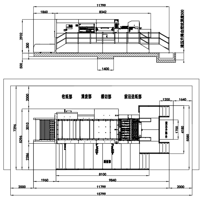
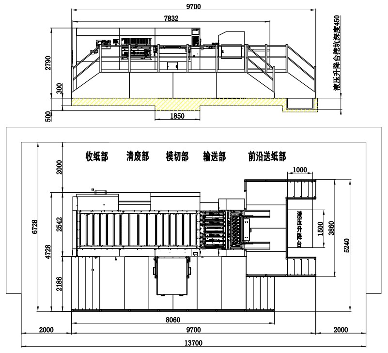
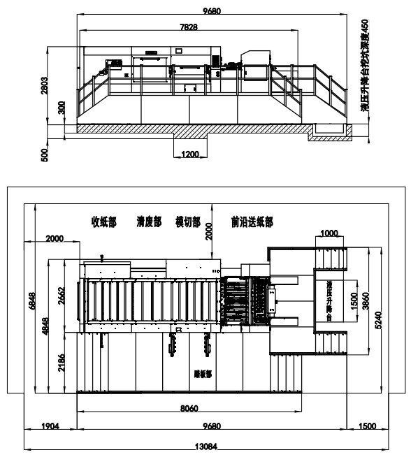
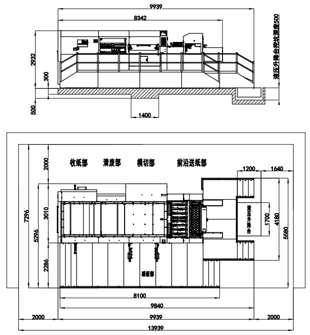
| Machine Dimensions(Stacking Delivery) | 9180×5240×2767mm(L×W×H) (L: paper prepared track included, W: platform included) | 9700x5240x2790mm(L×W×H) (L: paper prepared track included, W: platform included) | 9680x5240x2803mm(L×W×H) (L: paper prepared track included, W: platform included) | 9939x5580x2932mm(L×W×H) (L: paper prepared track included, W: platform included) |
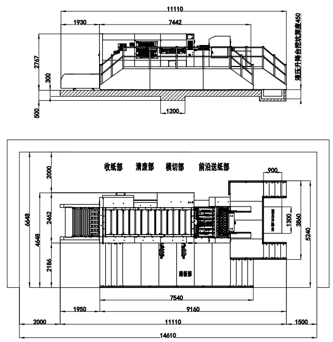
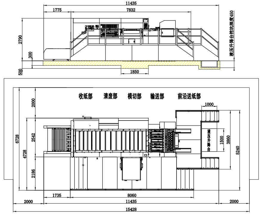
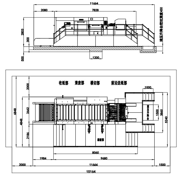
| Machine Dimensions(Batch Delivery Conveying) | 11110×5240×2767mm(L×W×H) (L: paper prepared track included, W: platform included) | 11435x5240x2790mm(L×W×H) (L: paper prepared track included, W: platform included) | 11664x5240x2803mm(L×W×H) (L: paper prepared track included, W: platform included) | 11799x5580x2932mm(L×W×H) (L: paper prepared track included, W: platform included) |
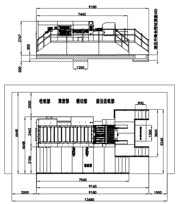
Drawing
Machine Dimensions(High Stack Collection)
MHK-1300FC
MHK-1350FC
MHK-1500FC
MHK-1650FC
Machine Dimensions(Paper Counting & Collection)
MHK-1300FC
MHK-1350FC
MHK-1500FC
MHK-1650FC